Install hardware
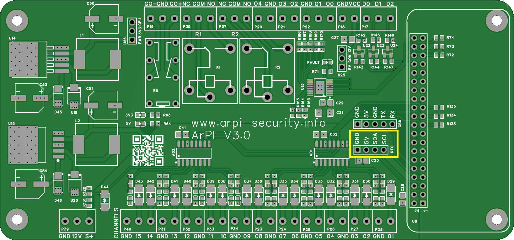
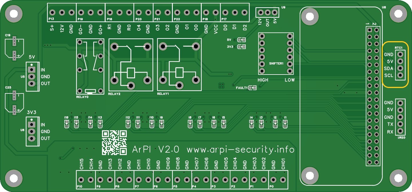
You can use the ArPI board for replacing the main board of an existing security system or building a new.
For that you need the following components:
- power supply (SCP-35/50-12 UPS)
- GSM module (SIM900)
- RTC module (DS3231)
- Wiegand keypad (Wiegand 26/34)
You can reuse the following components from the existing system:
- sensors
- syren
Warning
Be careful when connecting the components of the system. Wrong connections can damage the ArPI board or the connected components.
Connect the raspberry pi
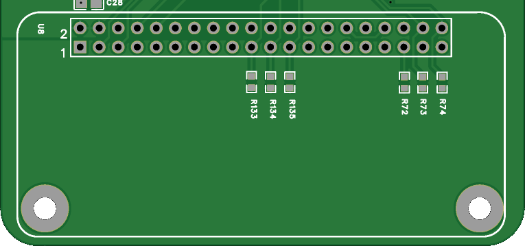
Connect the Raspberry Pi to the ArPI board with the 40 pin GPIO connector. The ArPI board is designed physically to fit under the Raspberry Pi 2 Zero, but you can use with other Raspberry Pi models as well.
When connecting to other models make sure the GPIO pins are aligned correctly. You can use a 40 pin GPIO extension cable for that with the correct orientation. See: Raspberry Pi GPIO pinout
Connect power supply
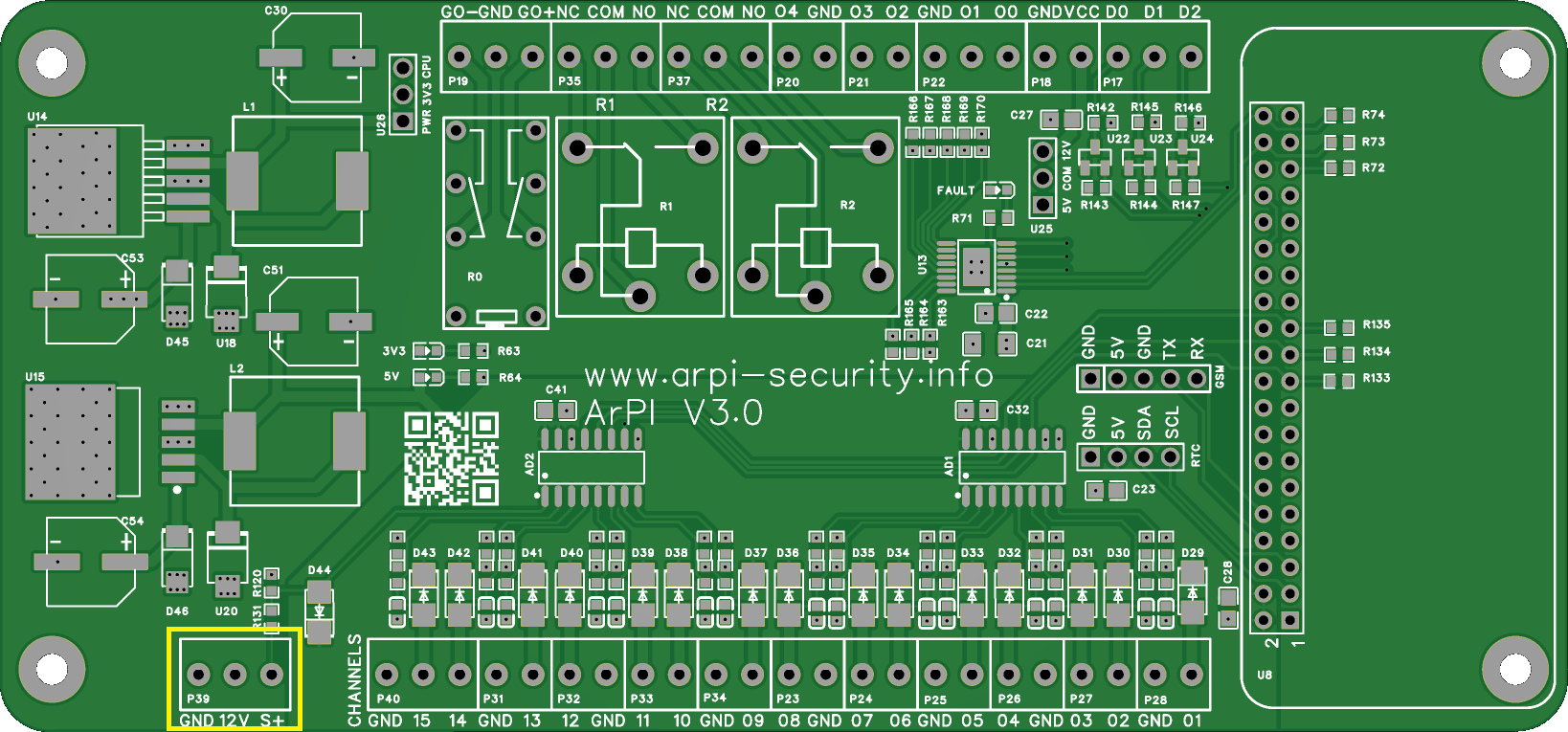
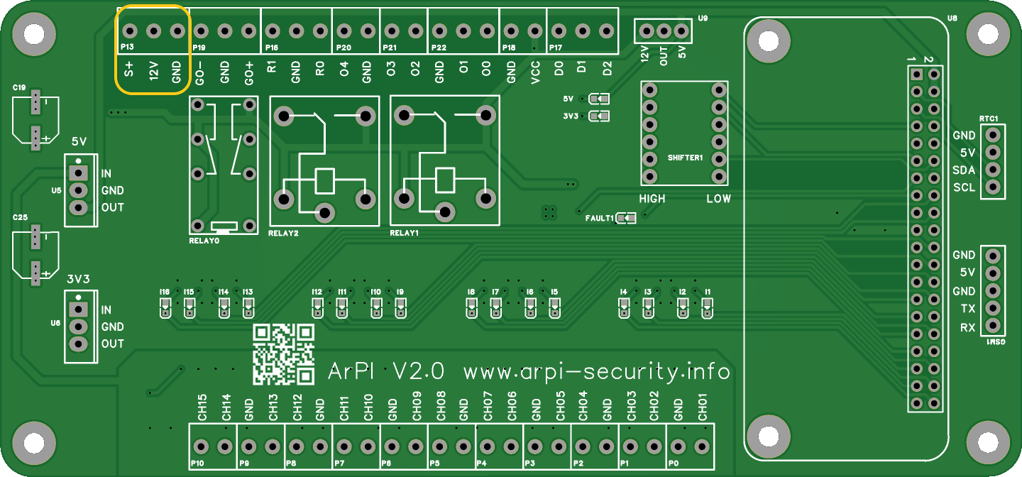
You need a 12V 5A power supply preferred with UPS battery backup (SCP-35/50-12 UPS). In case of an UPS power supply you can use the "S+" input for identifying the power outage by pulling it to ground.
Connect sensors
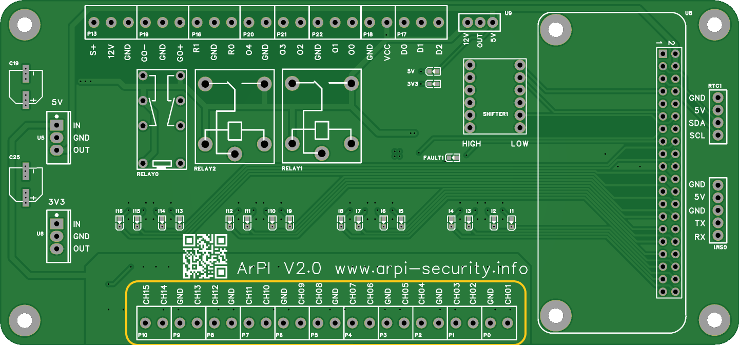
Sensors can be connected with NC/NO connections.
The V3 board supports 1 or 2 EOL resistors for each sensor and also zon doubling. For more information see Wiring sensors with V3 board.
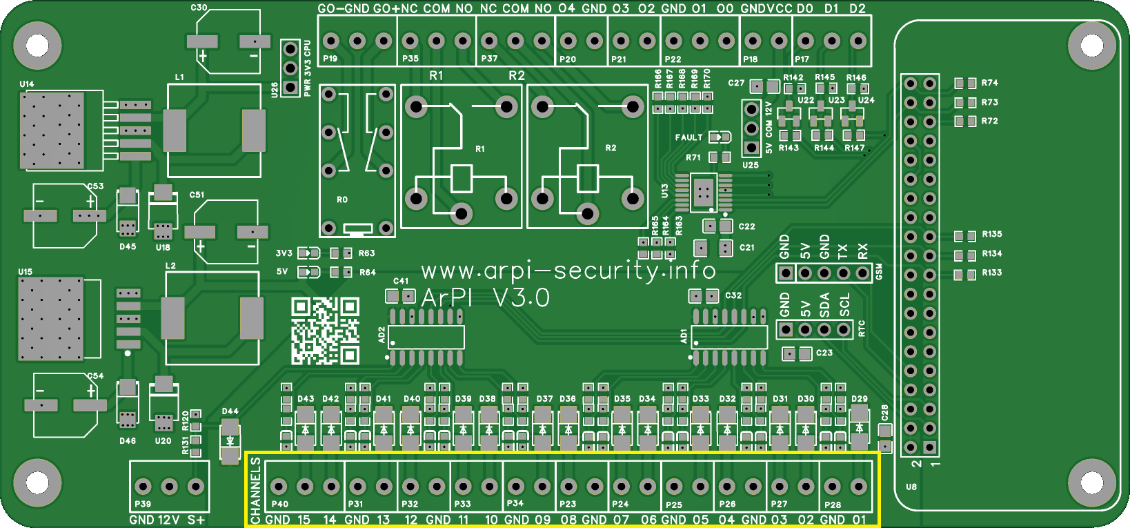
With the V2 board you have to use a single EOL resistor for each sensor.
Connect syren/outputs
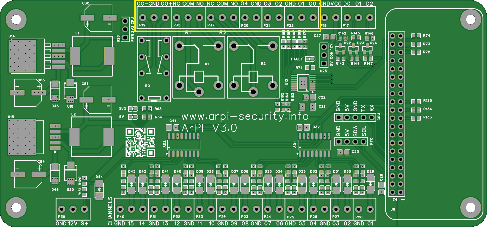
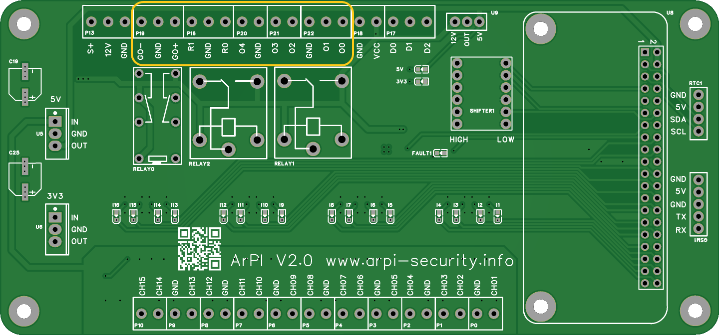
The syren can be connected to the GO+ or GO- terminals.
- The GO+ terminal will be pulled from GND to 12V when the syren should be activated.
- The GO- terminal will be pulled from 12V to GND when the syren should be activated.
Configurable outputs: * R0/R1 - relay outputs with NC/NO contacts * O0,O1,O2,O3,O4 - open collector outputs pulled up to 12V with 10k resistor
Connect Wiegand keypad
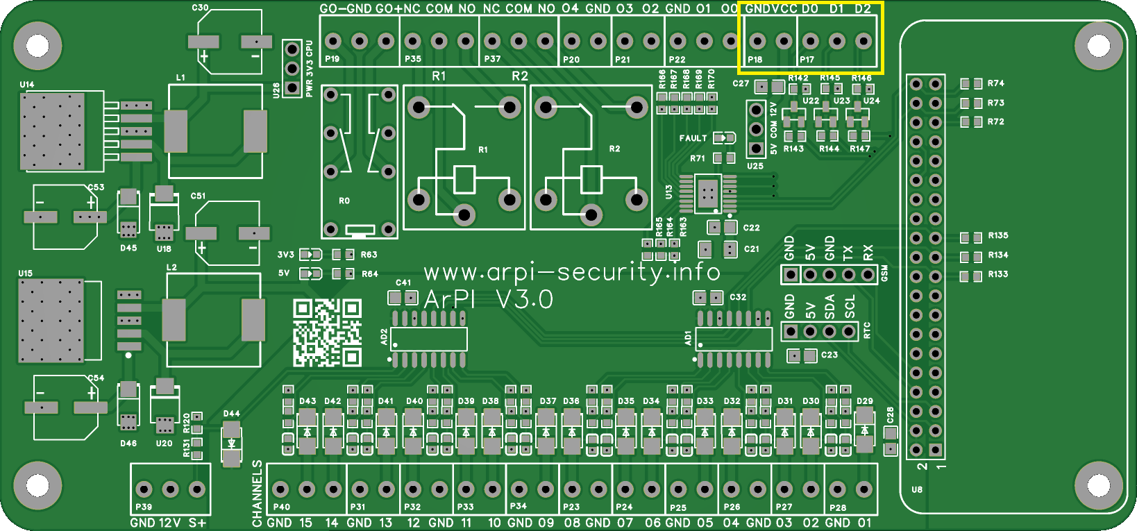
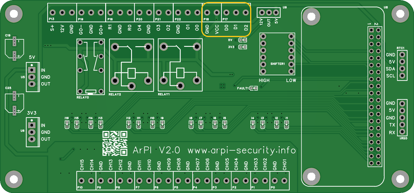
The keypads needs power supply and data connections.
- D0 - Wiegand Data 0
- D1 - Wiegand Data 1
- D2 - Wiegand doorbell
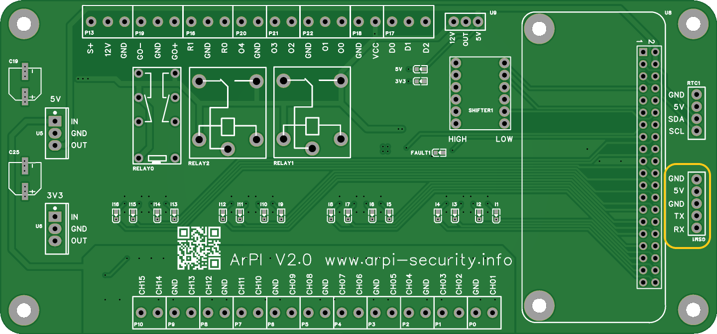
Connect GSM module
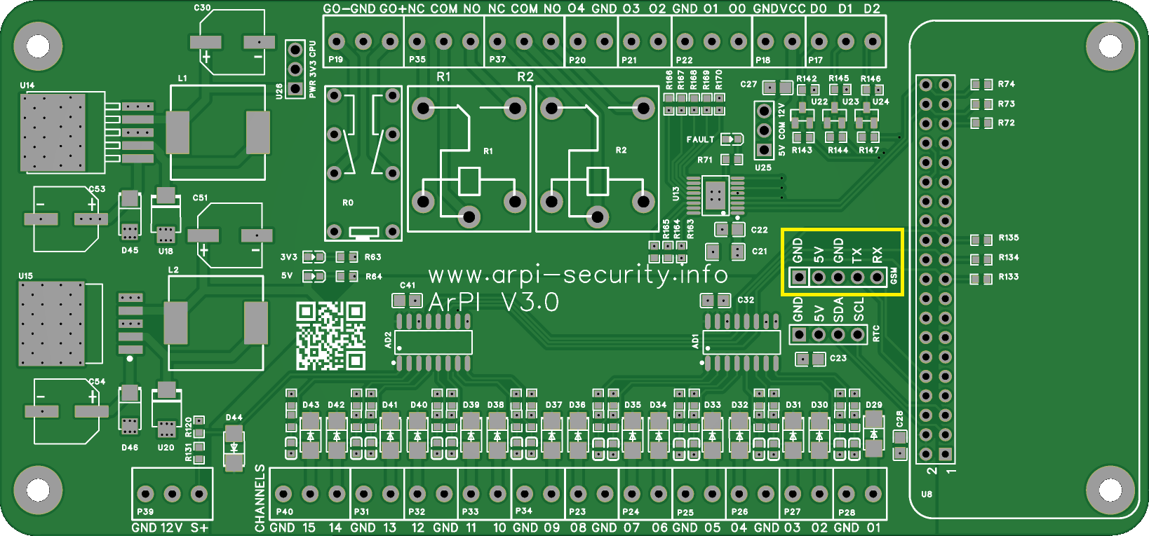
The GSM needs power supply and data connections.
- GND - GSM GND
- VCC - GSM VCC
- TX - GSM RX
- RX - GSM TX
Connect RTC
The RTC needs power supply and data connections.
- VCC - RTC VCC
- GND - RTC GND
- SDA - RTC SDA
- SCL - RTC SCL